When your garage needs more space but you’re not ready to compromise on capability, a customized solution is the way to go. In this post, team member Robert Shirley walks us through his weekend project: transforming a large, outdated workbench into a sleek, space-saving design inspired by The Family Handyman’s “Super Bench!” With clever modifications, repurposed materials, and a toolkit full of Simpson Strong-Tie fasteners, Robert Shirley shares his process—and the final result is equal parts practical and personal.
Embarking on a journey to optimize garage space while maintaining functionality, I undertook the challenge of downsizing my workbench, meticulously crafting a solution tailored to my needs. Inspired by Mark Petersen’s “Super Bench!” design from “The Family Handyman,” I ventured into a realm of modifications, scaling down dimensions and adding personalized features to suit my workspace. Armed with an array of tools including a table saw, orbital sander, drill, and an assortment of Simpson Strong-Tie fasteners ranging from structural wood screws to multipurpose fasteners, I embarked on a project of transformation.
Repurposing materials from my previous bench, including a prized Formica top, became a cornerstone of the endeavor, ensuring sustainability in the new creation. As I journeyed through the process, integrating under-shelf lighting, a multi-outlet power strip and an integrated pegboard, each addition was beholden to both practicality and my aesthetic vision. With every cut and screw driven, I sculpted not just a workbench, but a space-saving sanctuary infused with personalized touches, a testament to the joy of hands-on craftsmanship and the art of adaptation.
I previously had a workbench that was 96″W x 36″D x 66″H (including the upper shelf) taking up a ton of space in my garage. I wanted to downsize my work area to create more garage space, so I researched several workbench project plans and decided to use “Super Bench!” created by Mark Petersen of “The Family Handyman” (familyhandyman.com) as a reference. Mark’s bench is 72″W x 26″D and does not have an upper shelf; so I decided to modify his design by scaling it down to 52″W x 26″D x 66″H (total height). In doing so, I am altering Mark’s design by reducing the size and number of drawers and adding an upper shelf attached to tall rear risers.
Being spoiled by my previous bench’s thick Formica bench top, I decided to repurpose it for my new bench. In doing so, I have reduced its size using my table saw. I have also reused the original bench’s Formica upper shelf by scaling it down to size.
I added several new features to the bench as well, including under-shelf lighting, a multi-outlet power strip, floor protectors for the legs, a melamine lower shelf (not sure whether this was a good idea, but I think it looks good!), an integrated peg board and drawer slides.
Table saw, orbital sander, band saw (for cutting trim pieces, drill/driver, router, clamps, drill bits, hammer, tape measure, framing square, level, 90-degree corner clamps.
- (3) drawer handles
- (2) upper shelf support brackets — add an additional bracket if using a middle support for the upper shelf
- (3) sets of drawer slides — see below for size
- (8) leg-end floor protectors
- Optional small L-brackets for attaching workbench top to drawer encasement
- Stain or polyurethane
- Wood glue
| Quantity | Dimension | Description |
| 1 | 4′ x 8′ x 3/4″ | BC plywood (additional sheets needed if you are not repurposing workbench top and shelf) |
| 1 | 4′ x 4′ x 1/4″ | Plywood |
| 6 | 2×4 x 8’ | Douglas fir |
| 4 | 2×4 x 6’ | Douglas fir |
| Part ID | Quantity | Dimensions | Part Description | Material |
| A | 1 | 49″ X 22″ X 3/4″ | Drawer compartment top | Plywood |
| B | 1 | 49″ X 22″ X 3/4″ | Drawer compartment bottom | Plywood |
| C | 1 | 49″ X 22″ X 3/4″ | Bottom shelf board | Plywood or melamine |
| D | 1 | 52″ x 25 7/8″ x 1 1/2″ | Workbench top | Recycled Formica board, or 3/4″ plywood |
| E | 2 | 20 1/2″ x 3 1/2″ x 3/4″ | Drawer dividers | Plywood |
| F | 6 | 20 1/2″ x 3″ x 3/4″ | Drawer sides | Plywood |
| G | 4 | 14 1/4″ x 3″ x 3/4″ | Large drawer front/back | Plywood |
| H | 2 | 8 1/4″ x 3″ x 3/4″ | Small drawer front/back | Plywood |
| I | 1 | 56″ x 10″ x 1 1/2″ | Upper shelf | Recycled Formica board, or 3/4″ plywood |
| J | 2 | 15 3/4″ x 20 1/2″ x 1/4″ | Large drawer bottom | Plywood |
| K | 2 | 9 3/4″ x 20 1/2″ x 1/4″ | Small drawer bottom | Plywood |
| L1 | 4 | 1 1/2″ X 3 1/2″ X 35 1/4″ | Front Legs | Doug fir |
| L2 | 4 | 1 1/2″ X 3 1/2″ X 68″ | Back legs/shelf support | Douglas fir |
| M | 1 | 1 1/2″ x 3 1/2″ x 49″ | Drawer compartment back | Douglas fir |
| N | 2 | 1 1/2″ x 3 1/2″ x 20 1/2″ | Drawer compartment sides | Douglas fir |
| O | 1 | 1 1/2″ x 3 1/2″ x 38″ | Middle upper support (optional) | Douglas fir |
| P | 2 | 1 1/2″ x 3 1/2″ x 49″ | Bottom shelf front/back | Douglas fir |
| Q | 2 | 1 1/2″ x 3 1/2″ x 19″ | Bottom shelf sides | Douglas fir |
| R | 3 sets | 20″ x 1/2″ x 1″ | Side-mount drawer slides | Ball-bearing / steel |
| Part ID | Quantity | Dimensions | Part description | Material |
| A | 1 | 49″ X 22″ X 3/4″ | Drawer compartment top | Plywood |
| B | 1 | 49″ X 22″ X 3/4″ | Drawer compartment bottom | Plywood |


For this project, carefully study the assembly illustrations and component lists. I also recommend studying Mark Petersen’s assembly instructions in the Family Handyman version of this bench. The assembly instructions are similar (but differ where I made my aforementioned modifications). I use a variety of fasteners to secure various connections, and because I am using a heavy, Formica-laminated work surface and upper shelf, I am using load-rated fasteners (Strong-Drive SDWS Framing screws) to secure load-bearing connections in the legs, shelves and work surface support structures.
- Step 1 — Cut Wood Components to Indicated Sizes, except for the drawer components as these may need some fine-tuning after assembling the drawer encasement.

- Step 2 — Assemble the Bottom Shelf. Fasten the four (P, Q) 2×4 pieces to form the rectangular base of the bottom shelf, using one 3″ Strong-Drive® SDWS Framing screw per corner. Place bottom shelf board (C) on top of frame and fasten along the edges into the 2x4s using 1 5/8″ Deck-Drive™ DSV Deck screws (if using melamine, fasten with white painted-head Trim Screws). Screw spacing can be every 8″.
- Step 3 — Prepare the Drawer Encasement. Fasten the drawer encasement frame back (M) to the two 2×4 drawer encasement sides (N) using one 3″ Strong-Drive® SDWS Framing Screws per corner. Position the two drawer dividers (E) in their respective places by measuring from the inside edge of the encasement side member (N): the width of drawer slide (1/2″) + the width of drawer side (F) (3/4″) + the width of large drawer front/back (G) (14 3/4″) + the width of drawer side (F) (3/4″) + the width of (1/2″) drawer slide. Repeat the divider position measurements from the opposite inside edge of the encasement side member. Mark the outside of (M) where the dividers (E) meet it. Fasten the drawer dividers using the 3″ SDWS Framing screws.

Diagram 3 — Drawer Encasement Side View: Measurements for Determining Where to Position the Drawer Dividers (E) - Step 4 — Build the Drawers. Re-measure the drawer openings and cut the wood pieces for (G) and (H), referring to Diagram 1. Cut the drawer bottoms (J) and (K) so they are 1/4″ shorter than the drawer widths. Test fit each of the drawer pieces (along with the drawer slider guides to ensure all drawer components fit within the encasement. Assemble the drawers so that the drawer side edges will be exposed in the front. Fastening them this way will provide more strength and prevent the drawer front from pulling off if the drawer later contains heavy contents. Glue and clamp the sides together (I used 90° angle clamps at the corners). Fasten each end with four 1 1/4″ Deck-Drive™ DSV Wood screws (two per side). Repeat the process for the other two drawers. Using the manufacturer’s instructions, install the drawer guide pieces of the drawer sliders to the outside of each of the drawers’ sides. At this point one can test-fit the drawers, but I recommend waiting until later to insert the drawers into the encasement (after legs and bench top are installed) to keep the weight of the workbench manageable during the assembly.
- Step 5 — Assemble the Drawer Encasement. Place bottom encasement board (B) on top of frame and fasten along the three edges into the 2x4s using 1 5/8″ Deck-Drive DSV Wood screws. Screw spacing can be every 8″. Fasten board (B) along the drawer dividers by using the marks indicating the position of the drawer dividers (E) and extending a line across (B). Fasten (B) along these lines driving the 1 5/8— the Deck-Drive DSV Wood screws spaced about 8—. Flip the entire encasement over. Install the drawer guides per the manufacturer’s instructions. (Disassemble the drawer slide rails and install the “cabinet” guide pieces to the inner sides of (N) and on each side of the dividers (E). The “drawer” guide pieces will be installed onto the assembled drawers in later steps.) Attach the encasement board (A) repeating the steps required to install board (B).Using a framing square as a guide, secure the shorter front legs (L1) to the drawer encasement using two 3″ SDWS Framing screws.

Drawer Encasement Assembly with Drawer Components Positioned - Step 6 — Assemble the Legs. Preassemble the shorter front legs (L1) at right angles length-wise to each other (so they form a corner-shaped leg), as shown below, by fastening three 3″ SDWS Framing screws positioned at the top, middle and bottom of the legs. Repeat the same procedure with the longer back legs using five 3″ SDWS Framing screws, spaced at equal distances from the top to the bottom of the legs. Flip the drawer encasement upside down and position the front legs so the seams are facing the ends of the workbench and are being attached to the open drawer side of the encasement.

Two-Piece, Corner-Shaped Leg Assembly - Step 7 — Attach the Legs. Attaching the back legs (L2) may be a bit trickier and may require two people. Measure the length of the shorter front legs and mark that dimension on the longer back legs (L2). This will help position where the top of the drawer encasement should meet the back legs. Rest the workbench so that it is lying on the length of the front legs (basically, the open drawer end is facing the ground). Position the longer legs (L2) so the mark you made in the previous step aligns with the top edge of the drawer encasement. Using a framing square as a guide, secure the longer back legs (L2) to the drawer encasement using two 3″ SDWS Framing screws. Alternatively, invert the workbench project on top of two sawhorses so the installed legs point upwards. Then position (L2) so the mark from the previous step aligns with the top edge of the drawer encasement (which is now facing the ground). Place spacers under (L2) to help maintain the proper position relative to the drawer encasement. Then fasten. At this point, you can tap in the leg-end floor protectors (two per leg) to the bottom of the four legs.
- Step 8 — Apply Trim Pieces. Apply 3/4″ x 1/4″ screen mold trim pieces to exposed edges. Measure and cut the screen mold to fit each of the exposed plywood (or melamine) edges (drawer encasement top and bottom edges, vertical strips of the drawer dividers, bottom shelf edges). Affix with wood glue and fasten using the 3d x 1 1/4″ brads.

Install Screen Mold Pieces Cut to Fit Exposed Edges - Step 9 — Drawer Facings. Measure and cut the drawer facings (T) and (U). I then used a router to create a finished detail on the edges. Install the drawers into their respective positions in the drawer encasement by aligning the drawer guides within the cabinet guides. Position the drawer facings on each of their respective drawers, clamping them in place so they are centered horizontally, and the three drawers have their top edges aligned with each other’s. Fasten the facings to the drawer fronts from the inside of the drawer using the two 1 1/4″ Deck-Drive DSV Wood screws per facing.

Drawers and Bottom Shelf Positioned - Step 10 — Stain Prep. Adding the shelf and workbench top surface adds considerable weight to the project; before doing so — and assuming the project will need to be moved to another location — you may want to first stain and protect the wood using a polyurethane or similar product. To make things somewhat easier, remove the drawers from the encasement. Give all of the exposed parts a good sanding. Apply the stain or polyurethane coats per manufacturer’s recommendations. After the stain or polyurethane has dried, move the pieces back to your workspace.
- Step 11 — Bottom Shelf. Attach the bottom shelf. Determine how far off the ground you would like the shelf to be, and then cut four pieces of 2×4 from scrap to that height. These will serve as spacers providing the height of the shelf. Place these pieces of cut 2×4 under the bottom shelf assembly. Assuming the assembly is still upside down, lift the workbench over the bottom shelf, carefully flipping it right-side up, so that the bottom shelf assembly fits within the four legs. Secure the bottom shelf assembly to the workbench assembly using two 3″ SDWS Framing screws on each leg.
- Step 12 — Work Surface. Install the workbench top surface (D): Measure and cut sections out of the back corners of bench top (D) so the board will fit in and around the back legs or top shelf risers. In this case, the corner cuts were 3″W x 5″D. Apply an ample amount of glue to the top of the drawer encasement (A). Lift (D) on top of the workbench assembly sliding it back so that the newly cut back corners fit in the back supports. If your workbench top is plywood, fasten along the front, back and side edges using 1 1/4″ Deck-Drive™ DSV Wood screws.

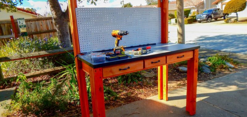
Assembled Workbench Top (stained, with polyurethane) - Step 13 — Top Shelf. Install the workbench top shelf (I): Install shelf brackets at the top of each of the back legs or shelf risers (L2) so the horizontal arm aligns with the top of (L2). Fasten with 1 3/4″ Strong-Drive® WSV screws. Lift the top shelf board (I) and position it on top of the back leg or the shelf supports and shelf brackets, aligning the shelf’s back edge with the back edge of (L2). Fasten with the appropriately sized screw for the thickness of (I). E.g., if (I) is 3/4″ thick, use 1/2″ or 5/8″ screws; if (I) is 1 1/2″ thick, use 1″ or 1 1/4″ DSV Wood screws. (If you suspect that you will be storing heavy objects on the top shelf and are concerned that the shelf will bow under the weight, attach a 2×4 that extends from the top of the workbench surface midpoint to the same height as the left and right rear legs/supports. Fasten to the 2×4 to the workbench via a metal strap or a bracket using 1 1/2″ screws, and then use a third shelf bracket to support the upper shelf.)

Install shelf brackets - Step 14 — Drawer Detail. Install drawer handles per manufacturer’s instructions.

Power Strip and Pegboard Installed - Step 15 — Peg Board. Install the pegboard by screwing the side edges into the rear-shelf support risers, using three 1 1/4″ screws per side.

Undershelf Lighting Installed - Step 16 — Finishing Touches. Install other customizations per manufacturers’ instructions: e.g., power strips, lighting, bench vises.
